

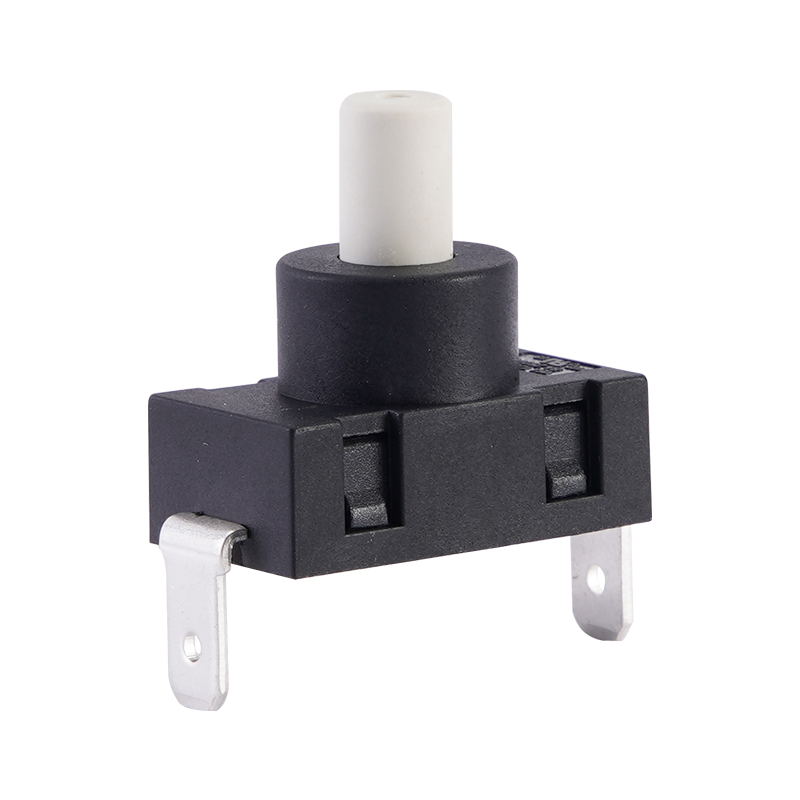
M12-05LB7-1H01OAND Waterproof microswitch
This is the selling point of the product
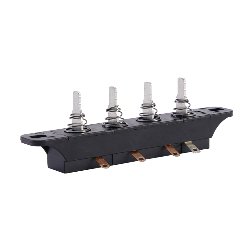
Compact size and structure
M12-05LB7-1H01OAND Waterproof microswitch
-

What's APP
13530287877 -

Skype
49047173@qq.com -

Wechat
13902627887
| PRODUCT SPECIFICATION | |||||||||||
|---|---|---|---|---|---|---|---|---|---|---|---|
| FILE NO. | M12-SPEC-5A | EDITION | A | ||||||||
| PART NO. | M12-05LB7-1H01S1ND | ||||||||||
| Product Name | Micro Switch | ||||||||||
| 1 | GeneralCharacteristics : | ||||||||||
| 1.1 | Application: This specification is applied to the micro switch (M12 water-proof series ) for Generalapplications. | ||||||||||
| 1.2 | Operating Temperature Range: -40℃to +125℃ | ||||||||||
| Preservative Temperature Range: -40℃to +125℃ | |||||||||||
| 1.3 | Operating Relative Humidity: ≤85%RH | ||||||||||
| 1.4 | Test Conditions: Unless otherwise specified, the atmospheric conditions for making measurements and tests are as follows: | ||||||||||
| Ambient Temperature: 5~35℃ | |||||||||||
| Relative Humidity: 45~85% | |||||||||||
| Air Pressure: 86~106Kpa (860~1060mbar) | |||||||||||
| 2. | Appearance, Structure and Dimensions : | ||||||||||
| 2.1 | Appearance: The switch shall have good finishing, and no rust, crack or plating defects. | ||||||||||
| 2.2 | Structure & Dimensions: Refer to individual product drawing. | ||||||||||
| 2.3 | Markings: Refer to individual product drawing. | ||||||||||
| 3. | Ratings | CERTIFICATION | RATING | LIFE CYCLES | FILE NO. | ||||||
| ENEC、CQC、VDE | 5(3)A/3(3)A/0.1A 125/250VAC 25T125 | 50,000 | VDE:40052877 | ||||||||
| 10(3)A 125/250VAC 25T125 | 10,000 | CQC20002247033 | |||||||||
| UL | 10(3)A/5(3)A/3(3)A/0.1A 125/250VAC 40T125 | 10,000 | E176026 | ||||||||
| 0.1A 30VDC 40T125 | 10,000 | ||||||||||
| 4. Electrical Characteristics | |||||||||||
| No. | Item | Criteria | Test Method | ||||||||
| 4.1 | Contact Resistance | 50mΩ max. | Measured by a voltage drop method at 1A Max, 5VDC. Any equipment with error not more than 5% can be used. Resistance after test is the average of 5 successive measurements.(To measure after operated 5 to 10 times) | ||||||||
| 4.2 | Insulation Resistance | 100 MΩ min. | 500VDC voltage is applied between each pair of terminals and between the terminal and the metal frame for 60±5S. | ||||||||
| 4.3 | Dielectric Voltage | No dielectric breakdown shall occur. | applied between non-connected terminals: before test:1000V 50-60Hz 10mA 60S after test:750V 50-60Hz 10mA 60S applied between terminals and the plastic or matel body before test:1500V 50-60Hz 10mA 60S after test:1125V 50-60Hz 10mA 60S | ||||||||
| 5. Mechanical Characteristics | |||||||||||
| No. | Item | Criteria | Test Method | ||||||||
| 5.1 | Operating Force | See product drawing | The Max. force of displacement of actuator from free position to operating position | ||||||||
| 5.2 | Releasing Force | See product drawing | The smallest force on the buttom when the actuator moved back from total travel position to release position | ||||||||
| 5.3 | Free position | See product drawing | The position where the actuator lead the Displacements when its out of force or the force is not enough to drive the actuator. | ||||||||
| 5.4 | Operating Position | See product drawing | The distance from the end of operating component to the center of mount hole when switch is being transformed | ||||||||
| 5.5 | Pre Travels | See product drawing | The distance vertically through, which the midpoint of the actuator (or tip of the shaft) trip move from its free position to operating position. | ||||||||
| 5.6 | Differential Travel | See product drawing | The distance from operating position to release position | ||||||||
| 5.7 | Over travel | See product drawing | The displacements of actuator form operation to total travel position. | ||||||||
| 5.8 | Terminal Strength | Shall be free from terminal looseness, damage and insulator breakage. The electrical performance requirements specified in section 4.3 shall be satisfied. | A static load of 50N shall be applied to the tip of terminal in a desired direction for 10 ± 1s. The test shall be done once per terminal. | ||||||||
| 6. Durability characteristics | |||||||||||
| No. | Item | Criteria | Test Method | ||||||||
| 6.1 | Mechanical Life | After test, Contact resistance: 500mΩ max. Insulation resistance:50MΩ min. The electrical performance requirements specified in item 4.3 shall be satisfied. The switch shall be free from abnormalities in appearance construction. Operating force: within ±30% initialization value. | 1,000,000 cycles of operation shall be performed continuously at a rate of 60 cycles per minute without load. | ||||||||
| 6.2 | Operating Life with Load | After test, Insulation resistance:10MΩ min. The electrical performance requirements specified in item 4.3 shall be satisfied. The switch shall be free from abnormalities in appearance construction. Operating force: within ±30% initialization value. | UL(UL61058):10,000 cycles of oper a shall be performed continuously at a rate of 15 cycles per minute with load as follow: Refer to individual product drawing (Resistive Load) | ||||||||
| CQC(GB15092.1)/ENEC(EN61058-1):50,000 cycles of oper a shall be performed continuously at a rate of 15 cycles per minute with load as follow: Refer to individual product drawing (Resistive Load) | |||||||||||
| 7. Weather Proof Characteristics 耐候性能: | |||||||||||
| 7.1 | Cold Proof | After test, Contact resistance: 500mΩMax.Insulation resistance:50MΩ Min. The Electrical performance requirements specified in item 4.3 shall be satisfied.The switch shall be free from abnormalities in appearance &construction. | After testing at –40 ± 2°C for 96 hours, the switch shall be allowed to stand under normal temperature and humidity conditions for 1 hour, and measurement shall be made within 1 hour after that. Water drops shall be eliminated. | ||||||||
| 7.2 | Hot Proof | After testing at 125± 2°C for 96 hours, the switch shall be allowed to stand under normal temperature and humidity conditions for 1 hour, and measurement shall be made within 1 hour after that. | |||||||||
| 7.3 | Moisture Resistance | After testing at 40± 2°C ,90~95% RH for 96 hours, the switch shall be allowed to stand under normal temperature and humidity conditions for 1 hour, and measurement shall be made within 1 hour after that. Water drops shall be eliminated. | |||||||||
| 7.4 | Temperature Cycling | After 4 cycles of following conditions, the switch can stay under normal temperature and humidity conditions for 2 hours, and measurement shall be made within 1 hour after that. Water drops shall be eliminated. | |||||||||
 | |||||||||||
| 8. Operating data diagram | |||||||||||
| OF :Operating Force OP : Operating Position TT :Total Travel RF :Release Force TTP: Total Travel Position TF :Total travel Force RP :Release Position FP : Free Position PT :Pre Travel OT :Over Travel DT : Differential Travel | |||||||||||
 | |||||||||||
Details
characteristic
parameter
| Place of Origin | Dongguan, Guangdong, China |
| Brand name | BAOKEZHEN |
| model | M12-05LB7-1H01OAND |
| Model Welding wire outlet direction | Arc button |
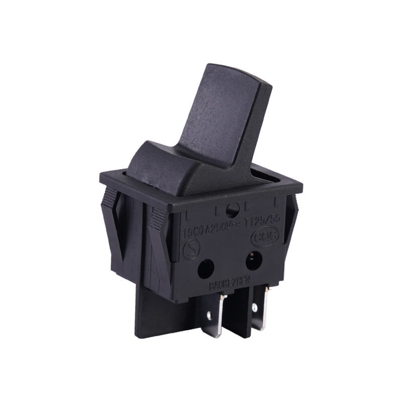
| Operating element type | Roller handle |
| Contact form | Single pole single throw |
| Safety certification | UL,VDE,ENEC,CQC。 |
| Quality assurance system of the company | ISO9001 and ISO14001 |
| application | Automobile, household appliances, toys, lighting equipment, Internet of Things |
| Waterproof and dust-proof IP67 design |
| Compact size and structure |
| Long life and high reliability |
| Solder wire terminal, other types of terminals are available, see the selection guide for details |
| Curved button, which can be equipped with various operating handles, see the selection guide for details |
| Rating | VDE、CQC、ENEC | 10(3)A 125/250VAC 25T125 | |
| UL | 10(3)A/5(3)A/3(3)A/0.1A 125/250VAC 40T125 | ||
| Operating frequency | electrical | 15cycles/minute | |
| Mechanics | 100cycles/minute | ||
| Initial contact resistance | 50mΩ Max | ||
| insulation resistance (at 500VDC) | 100M Ω Min | ||
| Dielectric strength | AC1,000V (50~60Hz) | ||
| Storage temperature | 25°C~+120°C | ||
| Storage humidity | 85%RH Max | ||
| life | electrical | UL: 10,000Cycles | |
| CQC、VDE、ENEC: 50,000Cycles | |||
| Mechanics | 1,000,000cycles | ||
7301-1B5AS-0P1 Micro Switch
Customers Also Bought
M08-P1CL1-H02OB-02 Waterproof microswitch last product:M08-P1CL1-H02OB-02 Waterproof microswitch
M12-10LB7-1W19OAND-07 Waterproof microswitch next product:M12-10LB7-1W19OAND-07 Waterproof microswitch